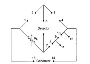
Measurement of resistance and inductance of coil using RLC Bridge
Introduction :
A bridge is an electrical circuit in which two circuit branches (usually parallel with eachother) are bridged by a third branch connected between the first two branches at some intermediate point along them. Bridge circuits find many applications both linear and non linear, including in instrumentation, filtering and power conversion.
LCR bridge is used to measure unknown resistance, capacitance and inductance. In LCR bridge the three arms are fixed and at fourth arm we connect unknown resistance, capacitance and inductance in parallel or in series to measure its value by balancing the bridge.
LCR bridge- In bridge  method the device under test is placed in a bridge circuit as as shown-
Its value can be determined from the setting for the other elements in the bridge. It is the LCR meters using this technique that are known as LCR bridge. An LCR meter is an instrument used to measure the inductance, capacitance and resistance.
- Test frequency :Electrical components need to be tested at the frequency for which the final product/application will be utilised. Common measurement frequencies are- 50/60 Hz, 120 Hz, 1 KHz, 100KHz and 1MHz. Most LCR meter today use an AC test signal over frequency range of 10Hz to 2MHz.
- Primary parameters L,C and R are not the only electrical criteria in characterizing a passive component and there is more information in the secondary parameters than simply Quality factor. There are different methods used to determine the values of L, C and R , these methods are as follows :
1. Bridge Method – This method use the familiar Wheatstone bridge concept as the basis of its operations.The aim is to concentrated for a condition where the bridge is balanced and no current flows through the meter.At the balance point the bridge component position can be used to determine the values of the component under test. This method is typically used for lower frequency measurements often measurement frequencies of upto 100KHz or so are used.2. Direct connection method :It is used for medium coil, select a frequency on the oscillator. Current limiting resistor is adjustable to fed select amount of current to the insertion resistor which is of small value of 0.2 ohm . This resistor acts as a voltage source which is shown as multiplying Q by meter. Connect the unknown resonant circuit by varying the oscillator frequency or by varying the capacitor condition. It is used for low Q coil.
In series RLC circuit the current flowing through all the three component i.e the resistor , capacitor and inductor remains the same but in parallel connection the voltage across each element remains the same and the current gets divided in each component depending upon the impedance of each component.
Specifications of digital LCR bridge :
1. Variable measurement R,L,C and Q.
2. Display : 3.5 digit.
3. Measurement range.
4. Inductance : 0.1-2000 H. Capacitance: 0.1pF – 2000micro farad
5. resistance : 0 ohm- 20M ohm
6. Q meter :The ratio of inductive reactance to effective resistance is known as Q factor or quality factor or magnification factor Q=2pi fL/R
Assumptions :
1. Intenal impedance of voltage source is neglected.
2. The capacitor is assumed to be non leaky.
3. Inverting capacitance is neglected.
Leave a Reply